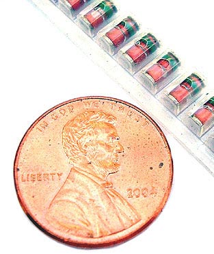
Zener diodes are a special type of diodes which permit current to flow in the forward direction as in a normal diode, but where it differs is that it also allows current flow in the reverse direction when the voltage exceeds the breakdown voltage also referred to as Zener voltage or the Zener knee voltage. This electrical property was discovered by Clarence Zener, which is how they got the name Zener diode.
The breakdown voltage can be controlled and fixed during the doping process of the diode’s production.
A zener diode can be used for a number of applications due to its properties. One such application is as precision voltage regulators. They are also used for clipping and coupling in many circuits.
A zener diode tester lets you test whether the zener diode is working properly and also tells the breakdown voltage of the diode. All that is needed is a 12 volt power supply, a 220 kilo ohm resistor, a voltmeter, a variable resistor, and the zener diode under test.
The Positive of the supply is connected to the variable resistor, and the negative and other end of the variable resistor to ground. The voltmeter is connected to the variable point of the resistor through the 220 k resistor. Another wire from the voltmeter connects to the test zener diode, and the other side of the voltmeter and the zener diode is grounded.
Increase the voltage and keep reading the value on the voltmeter, once the value stops increasing; the zener breakdown voltage has been reached. Reverse the diode and if the voltmeter does not show any reading then the zener diode is shorted.
As always, take proper precautions and know what you're doing before you assemble this tester. Need more specific directions? Try here.
Read more about
electronic components and electronic theory at http://www.westfloridacomponents.com.
No comments:
Post a Comment